9 minutes
Zhiyun Weebil-S BLE Protocol
Note: Source code for an example implementation is available here
Introduction
The Weebill-S is a mirrorless/DSLR camera gimbal made by Zhyiun that retails for around £389. It can be controlled either from the device itself or with a companion app on your phone via bluetooth. I purchased mine from ebay at a very reasonable price but with a defect, the onboard controls don’t work so you are required to use the app to control it.
The App
The ZY Play app is available for iOS or Android, via the Play Store or via a direct APK download from the site.
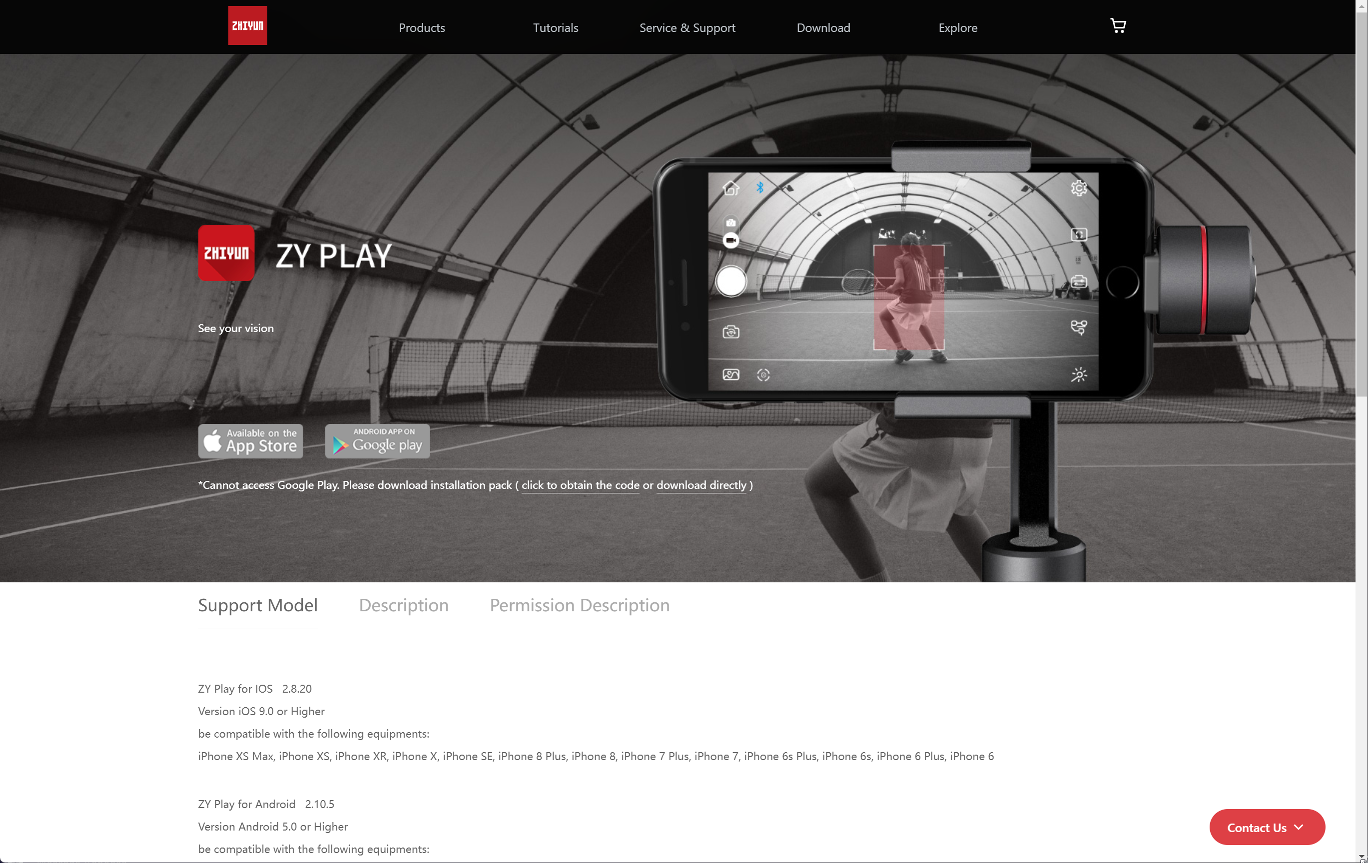
The ZY Play download page
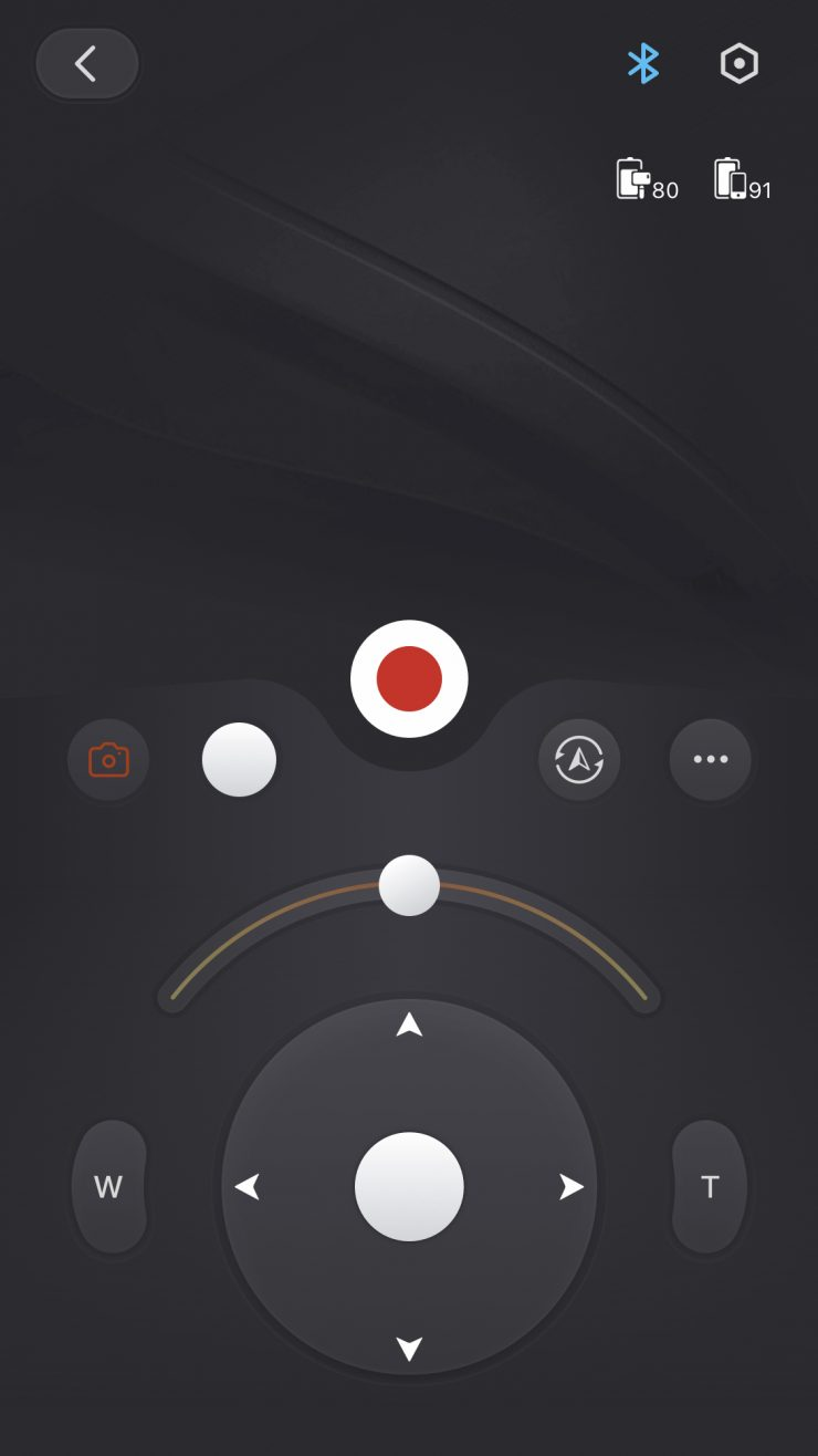
The ZY Play app
The app is quite disappointing. Whilst it allows for all the controls available onboard and even adds some timelapse functionality, the interface is difficult to use and the joystick control is essentially unusable because of how small it is. I felt like there was missing potential here, and after reading this blog post about BLE reverse engineering I decided to give it a try myself.
My first step was to attempt to decompile the app using the APK they helpfully provide on their site in the hopes that I could extract the bluetooth protocol from there.
But when I loaded up the decompiled app, I didn’t see the format I would expect. Instead, I saw a sparsely populated “WrapperProxyApplication” and references to a libtosprotection:
        java.lang.StringBuilder r9 = new java.lang.StringBuilder
        r9.<init>()
        java.lang.String r10 = "libtosprotection."
        r9.append(r10)
        java.lang.String r10 = CPUABI
        r9.append(r10)
        java.lang.String r10 = ".so"
        r9.append(r10)
        java.lang.String r9 = r9.toString()
Googling libtosprotection seems to point to it being an APK protection system created by Tencent.
There doesn’t seem to be much research out there about this with most links being completely in Chinese and
I certainly am not skilled enough to figure this out, so it was back to the drawing board.
Bluetooth HCI Snoop
I returned to the blog post from earlier and noticed the references to the Bluetooth HCI snoop log on Android. I enabled the logging in the developer options and started the app, connected to the gimbal and did some movements. I downloaded the log via ADB and opened it up in Wireshark.
I have barely any experience with Wireshark, especially not with Bluetooth so opening the file was quite intimidating. I scrolled until I saw the first communications with the gimbal and attempted to understand what I was looking at. After sifting through dozens of lines of communication setup, I finally got to a section where a clear command/response pattern was emerging.
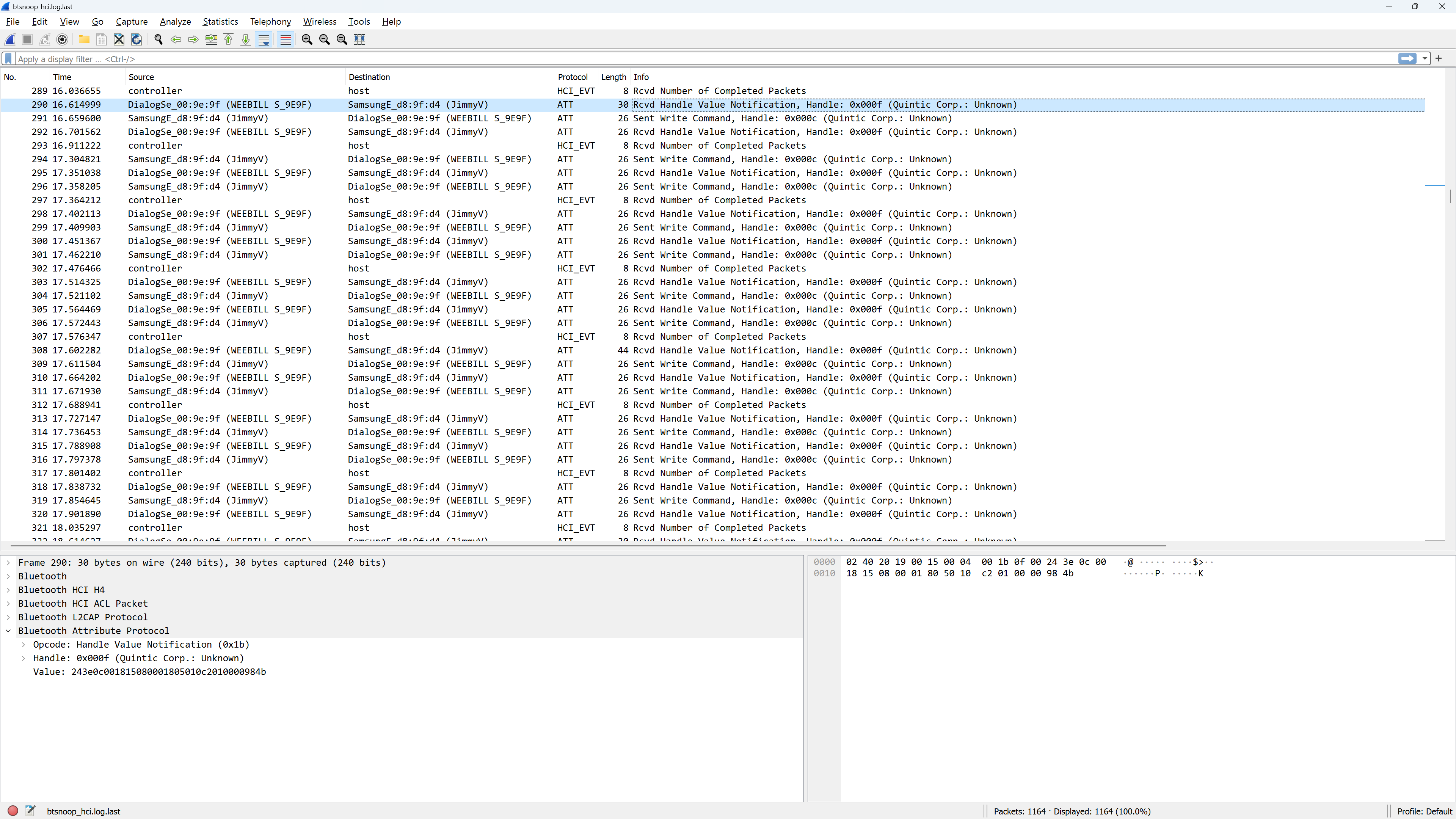
Bluetooth logs in Wireshark
I started to copy the values into a text file to see if I could deduce a pattern:
Sent: 243c080018120101020000006f76
Recv: 243e0800181201100200330507d8

Sent: 243c08001812020104000000169f
Recv: 243e0800181202100400cf007737

Sent: 243c0800181203010500000002ac
Recv: 243e08001812031005000800a08b

Sent: 243c080018120401020000006e35
Recv: 243e08001812041002003305069b
Immediately it was clear that there is a fixed start, a byte which increments by 1 each time, then some data:
Fixed        Inc 01 Cmd ??????????
243c08001812 03  01 05  00000002ac
243c08001812 04  01 02  0000006e35
After the increment, 01 seemed to indicate a command, and 10 a response,
the next byte I hypothesised would be a command ID since it was the same in both the command and response.
At this point, I thought I may have enough to attempt to send some commands to the gimbal using nRF Connect. Naively picking out commands and sending them to the gimbal didn’t seem to have any effect, at which point I went back to the Wireshark and saw data which complicated things:
Value: 243e0c001815080001805010c2010000984b
Value: 243c08001812370101100008b58d243c080018123801021000086ad3
This data broke multiple rules of my hypothesised format, it was clear that this was not going to be easy to understand without knowing more information about when the commands are sent.
Making a fake gimbal
If I couldn’t fake the app, then maybe I could fake the gimbal and get the app to connect to me.
This would allow me to read commands as buttons are pressed and send data back to validate the format.
For this, I chose to use Node.js with bleno to act as a BLE peripheral.

The gimbal's bluetooth signature
I opened nRF Connect to attempt to replicate the services and characteristics from the gimbal and quickly setup a fake version of the gimbal in bleno:
const bleno = require('bleno');
const userDescription = new bleno.Descriptor({
    uuid: '2901'
});

bleno.on('stateChange', (state)=>{
    console.log(state);
    if(state === "poweredOn"){
        bleno.startAdvertising("WEEBIL_S_9E9F");
        bleno.setServices(new bleno.PrimaryService({
            uuid: 'fee9',
            characteristics: [
                new bleno.Characteristic({
                    uuid: 'd44bc439abfd45a2b575925416129600',
                    properties: ['writeWithoutResponse'],
                    onWriteRequest,
                    descriptors: [userDescription]
                }),
                new bleno.Characteristic({
                    uuid: 'd44bc439abfd45a2b575925416129601',
                    properties: ['notify'],
                    onReadRequest,
                    onSubscribe,
                    descriptors: [userDescription]
                }),
            ]
        }))
    }
});
But when I opened the ZY Play app, it wouldn’t detect the “gimbal”. Puzzled, I returned to nRF connect to spot the difference:
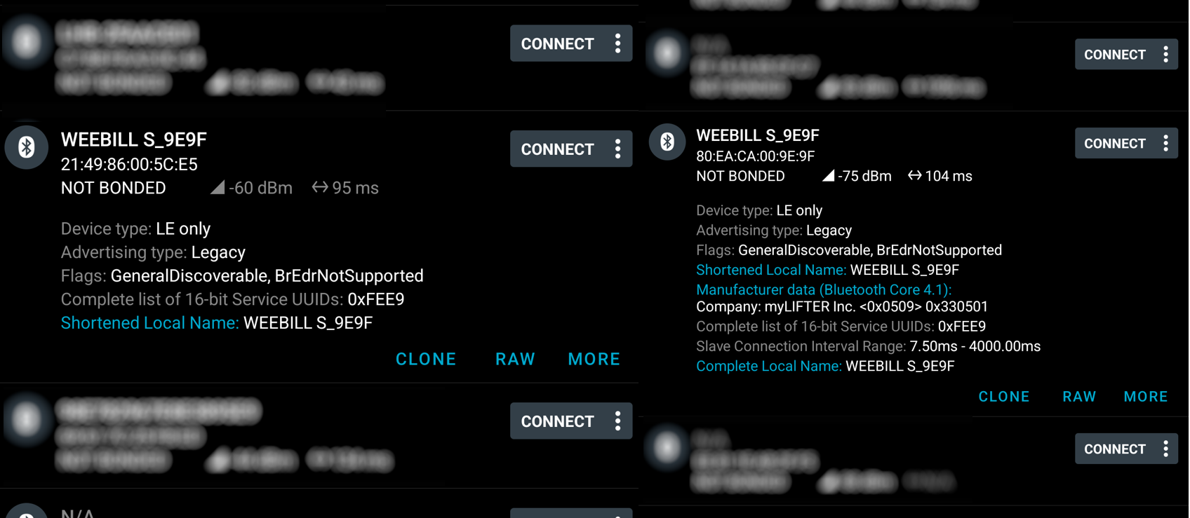
Missing fields on the fake gimbal
The characteristics and services checked out completely, but the fake gimbal was missing the “Manufacturer Data” and “Complete Local Name” fields.
Bleno did not seem to support adding either of those fields so I dug into the bleno code to see if it was possible to add.
Internally, startAdvertising created a buffer containing the device name and other advertising data and passed it to startAdvertisingWithEIRData.
Reading the docs I had initially dismissed this function as the docs state it is only available on Linux and I was running this on Windows.
Since startAdvertising just passed directly into the function, it must be supported on Windows so I copied the raw data from the fake gimbal
and added the manufacturer data field from the real gimbal and tried advertising again.
This time, I could see the app attempt to connect to my fake gimbal, repeat the same message 5 times and then disconnect with an error message on the app. This was good, as it meant I had a starting point. The app was clearly looking for a response and timed out when it didn’t get it after a number of retries. All I had to do was find the response to that command from the Wireshark and return the same responses.
Deciphering commands
At this point, I had a fake gimbal that the app could connect to, I just had to figure out the format for commands, then map each function on the app to a command.
After much tribulation, I came up with this rough format for commands:
Magic Len  ???? Inc 01 Cmd Data   CRC
243c  0800 1812 01  01 02  000000 6f76
Each packet starts with the magic bytes 24 3c. A single bluetooth transmission can sometimes contain more or less than one whole packet,
which is where the length argument is useful. The length is 2 bytes long and is Little-Endian, meaning that this packet has 0x0008 more bytes,
followed by 2 more bytes for the CRC.
The next 2 bytes still remain a mystery to me, but for almost all packets I have seen this has been 0x1812, except for the heartbeat message which is 0x1815.
I believe this may be some kind of format identifier as the heartbeat message does not follow the format described here.
Next up is a single byte increment value, which is incremented independently for each command and response. The app does not seem to require validate these, but the gimbal will ignore commands with duplicate increments.
The next byte is always 0x01 when sent from the app to the gimbal, and 0x10 when sent from the gimbal to the app.
The next byte is the command ID, followed by (usually) 3 bytes of arbitrary data. The length of this data is dictated by the remaining length from the length argument earlier. See the table below for known commands and their data argument structure.
The last 2 bytes contains a XMODEM CRC-16 which is calculated from after the end of the length argument to the end of the data argument.
Both the gimbal and app generate CRCs for commands/responses, however only the gimbal will ignore messages with an incorrect CRC.
Command IDs
These are the commands I have figured out so far, some of these I am certain about, some I’m not sure.
| ID | Meaning | Input Arg | Output Arg | Notes |
|---|---|---|---|---|
01 |
Tilt | 10 c2 followed by 01 for forward, 11 for reverse |
No Response | Moves the Tilt axis a tiny bit |
02 |
Pan | 10 c2 followed by 01 for forward, 11 for reverse |
No Response | Moves the Pan axis a tiny bit |
03 |
Roll | 10 c2 followed by 01 for forward, 11 for reverse |
No Response | Moves the Roll axis a tiny bit |
04 |
Get Software Version | Zeroes | 00 followed by the software version multiplied by 100. |
|
06 |
Get Battery Percentage/Set Tilt Pos | Zeroes / 10 followed by a 2 byte position position value` |
00 followed by the battery level. |
For some reason both battery level and tilt pos are the same command. This doesn’t happen anywhere else |
07 |
Set Roll Pos | 10 followed by a 2 byte position position value` |
No Response | Sets Roll axis to an exact angle. |
08 |
Set Pan Pos | 10 followed by a 2 byte position position value` |
No Response | Sets Pan axis to an exact angle. |
20 |
Press Button | c0 3c 00 |
No Response | Takes a photo/starts recording, other buttons may use the same format. |
22 |
Read Tilt Position | Zeroes | 00 followed by the Tilt position. |
Representation may be degrees/65535 but seems inconsistent. |
23 |
Read Roll Position | Zeroes | 00 followed by the Roll position. |
Representation may be degrees/65535 but seems inconsistent. |
24 |
Read Pan Position | Zeroes | 00 followed by the Pan position. |
Representation may be degrees/65535 but seems inconsistent. |
27 |
Set Mode | 80 followed by mode ID (see notes), followed by 00 |
No Response | PF = 00, L = 01, F = 02, POV = 03, GO = 04 |
7c |
Get Serial 1 | Zeroes | 00 followed by part of the serial number. |
|
7f |
Get Serial 2 | Zeroes | 00 followed by part of the serial number. |
|
7d |
Get Serial 3 | Zeroes | 00 followed by part of the serial number. |
|
7e |
Get Serial 4 | Zeroes | 00 followed by part of the serial number. |
|
61 |
Set Pan Smoothing | ??? | No Response | Something to do with smoothing settings |
62 |
Set Tilt Smoothing | ??? | No Response | Something to do with smoothing settings |
63 |
Set Roll Smoothing | ??? | No Response | Something to do with smoothing settings |
68 |
Get Camera Brand | Zeroes | 00 followed by the camera brand ID, see below table. |
|
70 |
Sync Motion Tilt Amount | ??? | No Response | Used to set Tilt sensitivity for Sync Motion |
71 |
Sync Motion Roll Amount | ??? | No Response | Used to set Roll sensitivity for Sync Motion |
72 |
Sync Motion Pan Amount | ??? | No Response | Used to set Pan sensitivity for Sync Motion |
Camera Brands
| ID | Brand |
|---|---|
00 |
None |
01 |
Canon |
02 |
Sony |
03 |
Panasonic |
04 |
Nikon |
05 |
CCS |
06 |
Fuji |
07 |
Olympus |
0a |
rcam |
0b |
bmpcc |
0c |
Sigma |
e0 |
Sony USB* |
*Sony USB has sub-types which I haven’t fully explored, they don’t appear to affect the ID.
Heartbeat Format
The heartbeat uses a different format from the normal messages:
Magic Len  ???? Inc 00 Mode Lock ???????      CRC
243e  0c00 1815 08  00 01   80   5010c2010000 984b
The format starts similar, but lacks a command ID or call/response argument. I haven’t figured out much about this one, yet.
The first byte of data is the mode, this is the same mode ID as used by command 0x27 - Set Mode.
The second byte is set to 0x80 when AXIS LOCK is triggered. I believe it may also change value for other states, such as sleep mode.